Mechanism
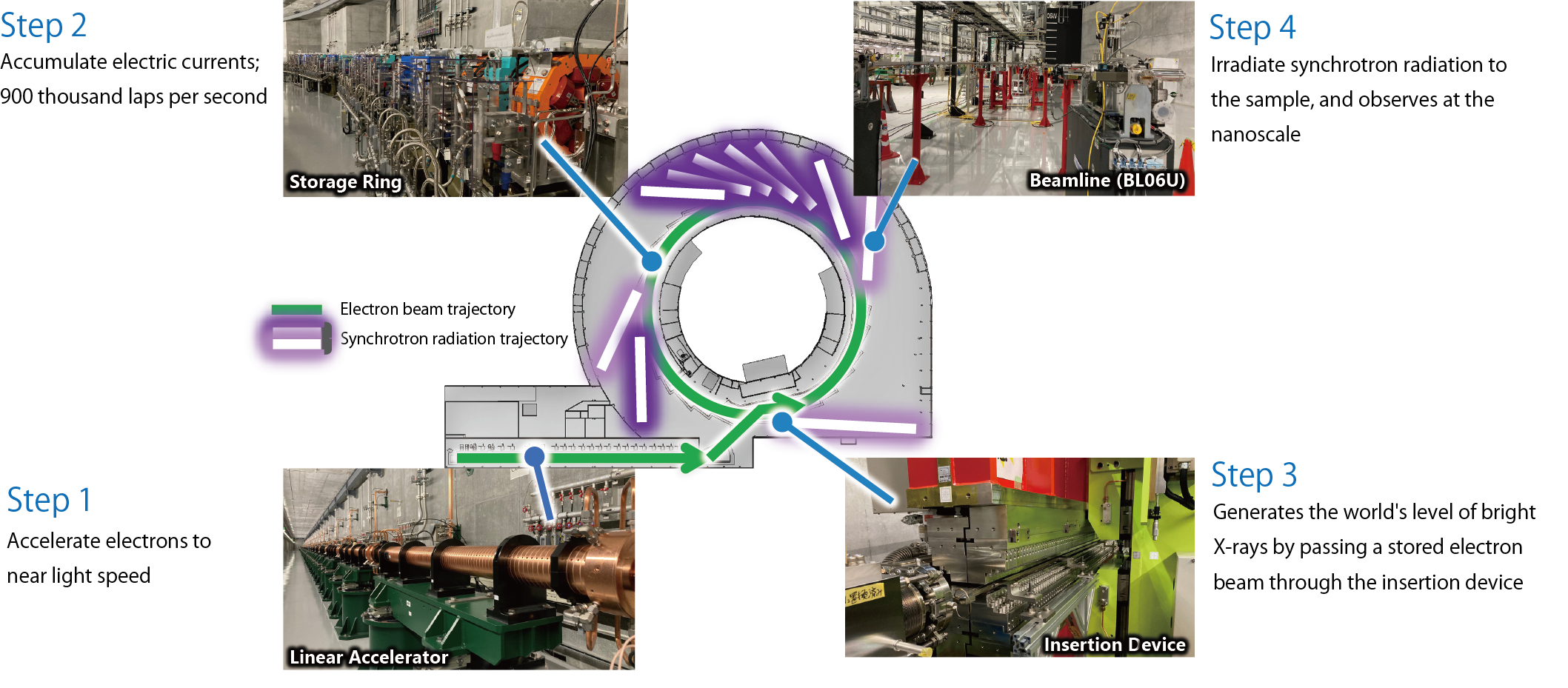
NanoTerasu consists of four major components, a linear accelerator, a storage ring, insertion devices, and beamlines, which generate synchrotron radiation in steps as follows.
Step 1
In the electron gun that generates electrons, a metal (Ba-impregnated tungsten cathode) heated to about 1000˚C is subjected to a voltage of 50,000 V (50 kV), drawing out a group of 10 billion electrons (electron beam). This electron beam is then accelerated up to 500 keV (500,000 electron volts) in a radio-frequency cavity.
Next, the electron beam with an energy of 500 keV passes through multiple electromagnets and a radio-frequency cavity called a “buncher.” At this stage, the electron beam is given a focusing force in the transverse directions (horizontal and vertical) and a compressing force in the longitudinal direction (traveling direction).
Through these operations, a high-density electron group called a “bunch beam” is formed. The generation of this bunch beam is completed in just 10 nanoseconds (one hundred-millionth of a second).
The bunch beam is accelerated (its energy increased) up to 3 giga-electron volts (3 GeV) by a 110-meter-long linear accelerator. In the linear accelerator, 40 accelerating structures are aligned with an accuracy of within 0.1 mm. The bunch beam passes through the accelerating structures, where a high electric field is generated, and gains energy from the accelerating field.
At NanoTerasu, a timing system capable of control with a precision of 300 femtoseconds (3 trillionths of a second) is equipped to ensure accurate acceleration of the bunch beam as it passes through the accelerating structures in an instant. The 3 GeV bunch beam accelerated by the linear accelerator is then transported through the beam transport line and injected into the storage ring from the inside of the ring.
Note: When an electron is accelerated by a 1.5 V dry cell battery, its energy becomes 1.5 electron volts (1.5 eV).
-3-1024x768-1.jpeg)
Step 2

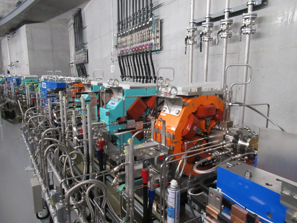
On the left side of the photo is the injection point where the storage ring and the beam transport line converge.
At this point, the transported electron beam is placed onto the electron beam orbit of the storage ring by momentarily activating magnets for injection. By repeating this injection process multiple times, the current in the storage ring is gradually accumulated.
To produce synchrotron radiation that enables high-precision measurements, it is essential to compress the electron bunch, which tends to spread out, into a high-density state. For this purpose, NanoTerasu’s storage ring adopts a state-of-the-art high-density magnet arrangement.
Each section (cell) is equipped with 4 bending magnets that steer the direction of the electrons, 10 quadrupole magnets that focus the spreading electrons, and 10 sextupole magnets that assist the quadrupole magnets and improve stability, forming a total of 16 sections (cells).
This enables NanoTerasu, despite being a compact facility, to produce synchrotron radiation with world-class brightness and phase coherence.
-2-1024x768-1.jpg)
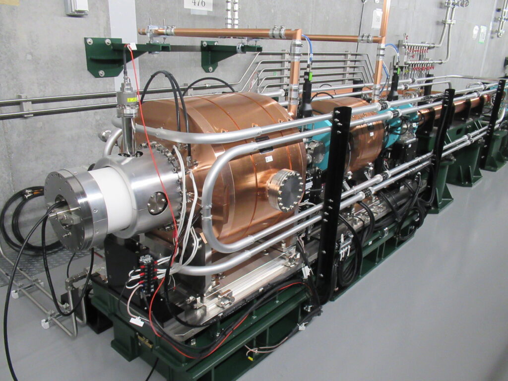
The electron beam circulating within the storage ring loses energy by emitting synchrotron radiation each time it completes a loop, due to bending magnets that steer the beam’s direction and insertion devices that make the beam oscillate. To compensate for this lost energy and maintain a constant energy level of the electron beam, high-frequency power is supplied to four copper radio-frequency (RF) cavities, each about 1 meter in diameter, shown in the left photo.
The electron beam loses approximately 1 mega-electron volt (1 MeV) of energy with each revolution. A device called a klystron, installed outside the storage ring tunnel, generates up to 1 MW of high-frequency power. This power is split into four branches above the tunnel and delivered to each RF cavity through waveguides—pipes that connect the top of the tunnel to the RF cavities.
Each RF cavity continuously receives up to 250 kW of power. To prevent the RF cavities from overheating, approximately 200 liters of cooling water per minute flows through the numerous copper pipes visible in the photo.
Step 3
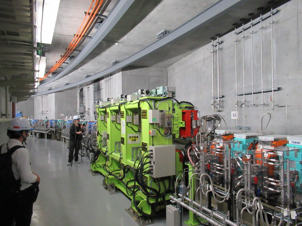
Inside the storage ring, insertion devices are installed to generate synchrotron radiation from the electron beam. An insertion device called an undulator consists of numerous powerful permanent magnets arranged in a regular pattern.
As electrons pass between the rows of magnets, they are bent by the magnetic field, generating synchrotron radiation. In an undulator, electrons oscillate and are bent repeatedly, allowing the production of more intense synchrotron radiation.
In the soft X-ray undulators at NanoTerasu, the arrangement of the magnet arrays can be adjusted, allowing the electron oscillation direction to be changed to horizontal, vertical, or helical trajectories.
This enables the polarization (orientation of the wave) of the generated synchrotron radiation to be controlled. Using various types of polarized light allows for more precise measurements.

Step 4

The beamline guides the synchrotron radiation generated by the insertion device to the experimental equipment. The synchrotron radiation must pass through a vacuum pipe approximately 50 meters long with an accuracy of within 1 millimeter.
The beamline first receives synchrotron radiation containing a range of wavelengths simultaneously and extracts only the wavelength needed for the experiment (spectroscopy). The extracted radiation is then focused onto the sample using devices such as concave mirrors (focusing). At NanoTerasu, synchrotron radiation can be focused down to the nanometer scale, enabling the measurement of samples far smaller than ever before.
The experimental equipment connected to the beamline is called an endstation. Each beamline is equipped with various endstations designed for different measurement techniques, where synchrotron radiation is used to irradiate samples for measurement.
The photo shows an endstation called RIXS at the public beamline BL02U. In this endstation, soft X-rays are used to irradiate a sample, and the scattered soft X-rays, which have lost a small amount of energy within the sample, are detected. By measuring the energy difference, the electronic states that determine the properties of the material can be revealed.